An Experiment in Tone
One day I was flipping through random electronics parts on AliExpress and came across a chip I hadn’t seen before—the TDA1524. After popping open the datasheet, it appeared to be a tone control chip with voltage-controlled inputs for Bass, Treble, Volume, and Balance. Apparently they use this chip in car stereos, karaoke equipment and other places where cheap tone control is needed. Best of all, it was a mere $1.30 for 10 pieces!
While patiently waiting the month-long shipping, I pondered whether this chip could form the basis of a voltage controlled filter / amplifier combo. Would it work? How would it sound? How long does it really take for 10 chips to pass customs?
Lucky you, you don’t have to wait. 🙂
Will it Filter? The results.
Of course it ISN’T a traditional VCF, because the cutoff frequencies for bass and treble seem to be fixed at 40hz and 16khz. That said, what makes this circuit unusual is that the chip both filters (through a 2-pole LP filter) and boosts the levels of the bass and treble depending on the control voltages. As such, when you turn up the bass, you definitely get the “Waa Waa” effect of a Low Pass filter as well as some interesting resonances and overtones.
I used a simple ramp wave as the input for this video. Towards the end I cranked up the volume to make it super hot, and that definitely gives you different sound control. 🙂
All of this creates some really interesting timbres, adding all kinds of overtones, etc. I tried to demo as many different sounds as possible—some great, some horrible, but I think there’s a lot of potential here.
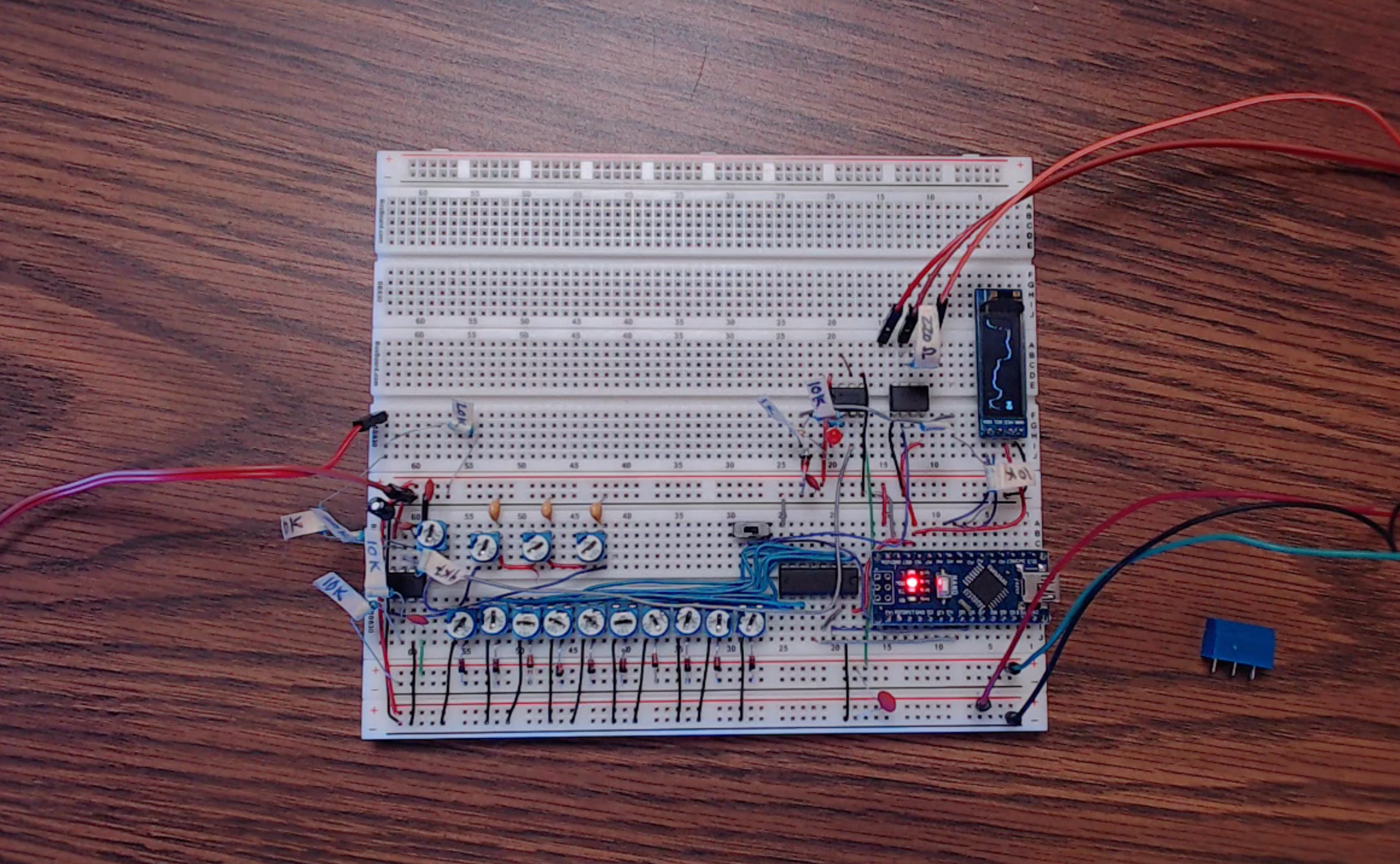
Pots from left to right:
- Feedback Attenuation / Resonance
- Input Attenuation
- Balance CV (0-5v)
- Bass CV (0-5v)
- Treble CV (0-5v)
- Volume CV (0-5v)
Hacking the TDA1524
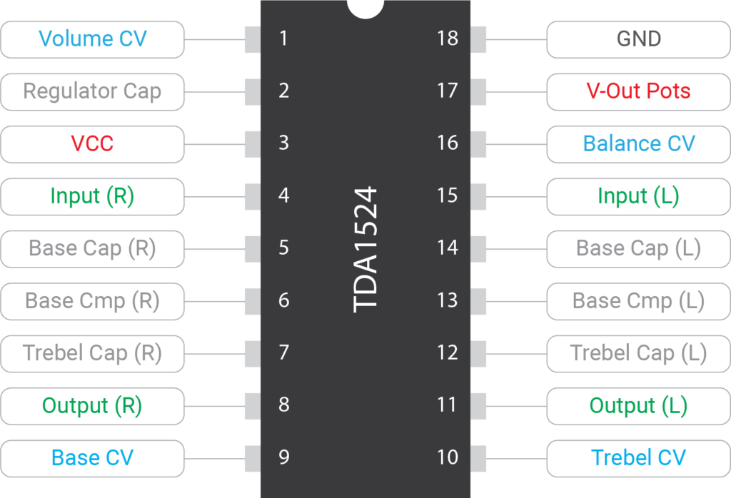
The chip is designed to control both left and right channels, but to enhance the effect, I fed the right channel’s output into the left channel’s input, and then use the left channel output as the signal out. This created something that sounds like a 4-pole low-pass filter, while the treble control gives you options for band-pass, high-pass, and band-stop filters as well.
The chip is designed for a much smaller input signal than a 10vpp, so I use a potentiometer to voltage divide the input.
Lastly, I mixed the left output signal with the input through a TL072 and sent it back into the right input to create a resonance feedback loop. This causes the filter to self oscillate. And while that oscillation can be made to sound really harsh, you can also get much softer and more musical sounds out of it as well. One strange effect I noticed was that the resonance seems to quantize itself to the harmonic series (you can see it around 1:23 in the video above). I’d never heard that one in a filter before.
VC Tone Filter Schematic
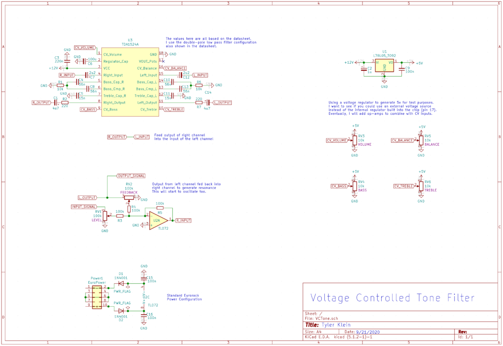
The schematic uses surprisingly few parts. The basic filter portion follows the datasheet, but pin 8 (right output) routes into pin 15 (left input) to double up the filter. I’m guessing you could probably remove one of those capacitors (C1 or C12). Work in progress 🙂
Because the left channel feeds into the right channel, the balance CV needs to stay around 2.5v to produce sound. Otherwise, you are effectively turning the right channel up and the left channel down, or visa-versa. Either way, you attenuate the output. Small changes around that 2.5v mark do create some interesting sound variation though, especially if you swap in different capacitor values for C4/C5/C8/C10/C11/C13. If the left/right channels aren’t balanced, then you will get tone variation as you change how the two blend together.
One last thing, the datasheet shows that the TDA1524 has an internal voltage regulator that you can use to drive your CV pots. I deliberately used an external regulator here in order to demonstrate that an external voltage can be applied instead.

